
CONTENTS:
1 - Antenna Placement
2 - Mast
3 - Coax Cable Installation
4 - Ground Wire
5 - Antenna Grounding
6 - Parts List
Proper antenna installation will get the best signal possible and be durable. It will also provide as much protection as possible from lightning strikes. This page describes installation from the National Electrical Code (NEC) and industry standard practices.
| ANTENNA | |
|---|---|
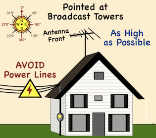
| • | As High as Possible. |
| • |
Find Pointing Angles (Tower Locator). |
| • | Clear Line-of-Sight to Towers. |
| • |
- Avoids signal interference. - Dangerous to work around. - Reduces accidental line contact. |
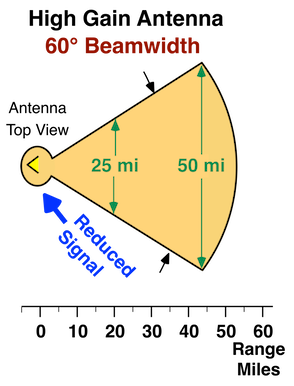
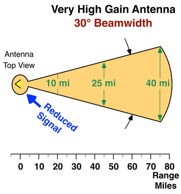
Antenna Pointing Angle
The antenna should be pointed such that the towers are within about 60° for a high gain antenna, and 30° for a Very High Gain antenna. An antenna will still receive a signal that is out of the beam, but at reduced power. The more out of the beam the lower the signal.

A smartphone compass app can be used to determine True North. When using a magnetic compass account for the difference between True and Magnetic north (changes with time). See NOAA's Magnetic Declination Website. Note that local conditions could effect magnetic readings. If possible use landmarks to confirm or establish true north.
|
• Circular Tubing • 5 - 6 feet long. • 1.25 inch outer diameter. • 18 gauge galvanized steel. Never connect more than 2 sections. |
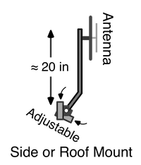
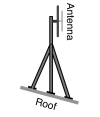
MAST MOUNTS
There are various types of mast mounting hardware. Mounting brackets have different stand-off spacing lengths. Use a spacing that ensures the mast clearance needed. Two or more mounting points has better wind resistance than a single point mount.
| Chimney Mount |
|---|

|
| Eave Gable Mount |
|---|

|
| Side Structure Mount |
|---|

|
| Side or Roof Mount |
|---|
|
| Tripod Roof Mount |
|---|
|
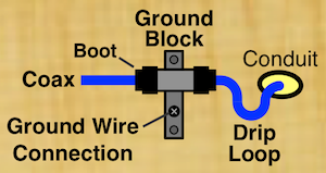
Protect all outside coax cable connections with a weather boot. This includes connecting to the antenna, ground block, and cable-to-cable.

| INSTALLATION |
|---|
|
Quad Shield recommended. RG-59 or RG-11 will work. See Hardware / Cables. |
|
Use a connector Weather Boot. |
|
Loop Coax Cable Around Mast.
Extra cable for repairs. |

Secures to structure. Reduces wind loosening cable connections. |
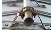
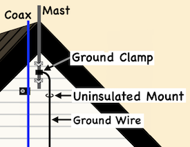
Connect a ground wire to the antenna mast with a ground clamp. Secure the ground wire to the structure using uninsulated (or insulated) mounts.
|
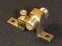
Mast Ground Clamp
Copper (Cu) or Bronze 
|
|
|
Ground Wire Options American Wire Gauge (AWG) | |
| AWG 10 | - Solid Copper Wire |
| AWG 17 AWG 17 |
- Bronze - Copper-Clad Steel |
| • | Uninsulated or Insulated Wire Some local codes require green insulation. |
|
• • • • |
Continuous, no splices Run as straight as possible Inside or Outside Insulated mounts not required |
COAX GROUND BLOCK |
|---|
|
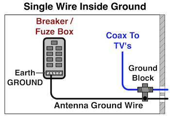
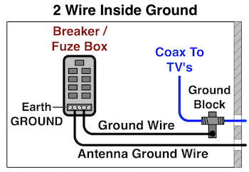
There are 2 methods for grounding antennas and cables, Single Wire Common Ground and 2 Wire Parallel Ground. Both methods are permitted by the National Electrical Code (NEC). Some local electrical codes require a 2 Wire Ground, and some require insulated ground wires must be green. A two Wire Ground is recommended for antennas with a preamp or rotor.
|
Single Wire
Common Ground
|
|
2 Wire
Parallel Ground
|
|
Some local codes have additional requirements.
-- 2 Wire Parallel Ground System . -- An insulated ground wire must be green. |

|

|

EARTH GROUND
The antenna and cable ground wire connect to the electrical service earth ground electrode also called power ground rod. The power service ground rod runs directly from the power meter into the ground. A copper (Cu) or bronze ground clamp or a bonding termination is used to connect the ground wire to the power service ground.

An antenna mast or cable within 5 feet of a swimming pool must be bonded to the pool bounding grid (ground).
INSIDE GROUND
The Ground Block can be mounted just inside the home, and the Ground Wire can connect to the earth ground terminal in the power breaker/fuze panel.
Basic tools needed include a ladder and assorted screwdrivers, wrenches, sockets, and maybe a hammer etc. You will also need a wood and/or concrete drill, and appropriate drill bits and screws.
| Quantity | Description |
|---|---|
| 1 | Antenna (see Antennas) |
| 1 | Mast & Mountings |
| 1 | Coax Ground Block |
| Feet | Coax Cable (see Cables) |
| Feet | Ground Wire |
| 1 to 3 | Coax Connector Weather Boots |
| 1 to 3 | Ground Clamp |
| 0 to 1 | Bonding Termination |
| multiple | Insulated Cable Straps |
| multiple | Uninsulated mounts. |
| multiple | Tie Wraps / Zip Ties |
| multiple | Screws, washers, etc. |
|
OTA DTv TV Antenna Installation |
|
|---|