Television Antenna
Types and Options
| CONTENTS | ||
|---|---|---|
| INTRODUCTION | ANTENNA THEORY | |
|
• Indoor Antennas
• Outside Antennas • Multi-Directional Antennas |
• Antenna Gain
• Reception Beam • Cell & FM Interference |
|
| CONTENTS | ||
|---|---|---|
| INTRODUCTION | ANTENNA THEORY | |
|
• Indoor Antennas
• Outside Antennas • Multi-Directional Antennas |
• Antenna Gain
• Reception Beam • Cell & FM Interference |
|
INTRODUCTION
Indoor antennas get signals within 20 to maybe 35 miles. Outside antennas get signals within 45 to 60 miles or more. A cluttered environment will reduce range. An antenna preamp can improve reception. Some antennas come with built-in or attachable preamps. A preamp mounted close to the antenna can be added to any antenna. Preamps require power, house current (110-120 Vac) or USB power.
Digital vs Analog Antennas
There is no difference between an Analog and Digital (HD or 4k UHD NextGen) antenna. Digital and analog TV signals both use the same carrier frequencies. Carrier modulation (digital or analog) does not effect antenna reception.
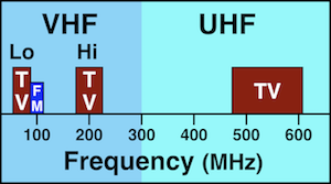
Frequency Bands
All TV antennas receive the UHF frequency band. Many also receive VHF-Hi, and some also get VHF-Lo. Nationwide 80% of TV channels are in the UHF band. Only 15% are in VHF-Hi, and 5% in VHF-Lo. Most antennas will receive out of band signals if the signal is strong enough.
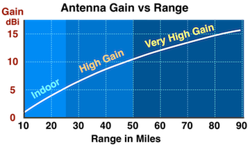
Antenna Gain
Gain is a better measure of antenna performance than published range (often exaggerated). Antenna gain is the signal power captured and measured in dBi. It is sometimes expressed in dB, but they really mean dBi. See Antenna Gain below.
Reception Beam
Most antennas are directional and have reception beams. High gain antennas have beams 60° to 70° wide. Very high gain long range antennas have beams 15° to 35° wide. Symmetrical antennas (looks the same from the front and back), have the same reception beam and gain in the front and back. See Reception Beam below.
Size
The larger an antenna the greater the gain, and the more narrow the reception beam.
Summary
| Antenna Options | |
|---|---|
|
Type - Indoor - Outdoor |
Frequency Band(s) - UHF - VHF / UHF - VHF-Hi / UHF |
| Gain (dBi) | Preamp optional |
| Typical Specifications | ||
|---|---|---|
| Antenna Gain: | 2 - 5 2 - 9 |
dBi (UHF)
dBi (VHF) |
| Range: | 20 - 30 | miles |
| Reception Beam: | 60 - 90 | degrees |
Indoor antennas are relatively low gain and come in various configurations. Some are wall or window mounted, some are table top, and some can be either.
| UHF Antennas | |
|---|---|
|
Loop Antenna -- Gain: 4 to 5 dBi -- 6 to 9 inch diameter |

|
|
Flat Thin Antenna
-- Gain: 1 to 4 dBi -- 12 to 17 inch wide |

|
| VHF Antenna | |
|---|---|
|
Rabbit Ears Dipole -- Gain: 2 to 9 dBi -- Extends 13 to 52 inches -- Adjustable angles |

|
| VHF / UHF Antennas |
|---|
|
Outside antennas have greater gain and are mounted higher and in the open where the signal density is greater.
Antenna Profiles
There are 2 basic antenna profiles, horizontal and vertical.
Vertical profile antennas are a little more efficient.
Symmetrical vertical antennas have both front and rear reception unless they have a reflector.
Antennas with a reflector have more gain.
| Horizontal Profile |
|---|

|
| Yagi (VHF) |
| Log-Periodic (UHF) |
| Vertical Profile | ||
|---|---|---|
|

|
|
| Loop Array / Dipole | Loop Array / Reflector | |
| Front & Rear Reception | Higher Gain | |
High Gain and Very High Gain Antennas
Most outside antennas are High Gain.
Very High Gain antennas have greater range, are larger, and have a more narrow reception beam.
Antenna types include Yagi, Lop Periodic, Loop, Bowtie, Dipole, or a combination of types.
| Antenna | High Gain | Very High Gain |
|---|---|---|
| Gain | 5 - 10 dBi | 11 - 20 dBi |
| Beam | 60° - 70° | 15° - 35° |
| Range | 45+ Miles | 60+ Miles |
| Size | Moderate | Large |
| Band |
VHF / UHF VHF-Hi / UHF UHF |
|
Rotor Antennas
These antennas can receive signals from all directions. The rotor requires a power and control cable run to the outside rotor motor. The antenna does take a little time to change directions. The rotation is plus or minus 180° (so the coax cable doesn't wrap around the mast).
A rotor can be added to any antenna, some antennas come with a rotor.
|
Rotor Antenna
• 360° Coverage. • ± 180° Rotation. • Takes a little Time to Change Angles. • Power / Control Cable to Outside Rotor. |
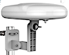
Omni Directional Antennas
These antennas can receive signals from all directions simultaneously. They are relatively compact and widely used in marine and recreation vehicles, and homes. Most have built-in preamps. Overall performance is modest, a strong to high normal signal is required.
|
Omni Antenna
• 360° Coverage. • Modest Range. • Small and Compact. • Most have a Built-in Preamp. |
| ANTENNA THEORY |
|---|
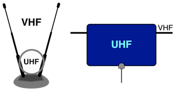
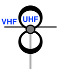
VHF antennas are larger than UHF antennas because the wavelengths are longer (lower frequencies). A VHF/UHF antenna combines a VHF and UHF antenna into a single configuration. A built-in coupler is used to combine VHF and UHF signals to the antenna output connection.
ANTENNA GAINTelevision antenna gain is usually measured in dBi. Sometimes dBi is shorten to dB. Some shortwave antennas are measured in dBD. Both dBi and dBD use a base 10 logarithmic scale.
| dBi |
|---|
|
Decibels above or below a Lossless Isotropic Radiator. |
| dBD |
|---|
|
Decibels above or below a Standard Half wave Dipole antenna with a gain of 2.15 dBi. |
| dBi | = | dBD | + 2.15 |
| dBD | = | dBi | - 2.15 |
|
Convert dBi to / from dBD |
|---|
|
Convert to dBi |
ESTIMATE UHF ANTENNA GAIN FROM SIZE
UHF Antenna gain can be estimated from antenna dimensions and efficiency .
Efficiency can be estimated from antenna type.
Gain also depends on signal frequency, the higher the frequency the greater the gain.
|
G A f η |
- Gain (dBi) - Area - Frequency (Hz) - Efficiency (%) |
c π |
- Speed of Light - Pi (3.14159...) |
| Antenna Type | Efficiency |
|---|---|
| Indoor Antenna | 20 - 30% |
| Horizontal Profile | 50 - 60% |
| Vertical Profile | 60 - 75% |
|
Estimate UHF Antenna Gain from Efficiency, Length & Width |
||
|---|---|---|
| RF Channel: | ||
| Length: | inches | |
| Width: | inches | |
| Efficiency: | % | |
|
RF Channel | ||
Most antennas are directional and have a specific reception area (main beam).
|
RECEPTION PATTER |
|---|

|
|
BEAM SPREAD (d) |
|---|

|
|
Beam Spread Calculator |
||
|---|---|---|
| Beamwidth: | ° (Degrees) | |
| Range: | ||
|
Beamwidth | ||
UHF antennas with a preamp and close to a Cell tower (4G/5G) may get strong signals that interfere with the preamp. You may lose some or all TV signals. Some preamps have a Cell signal (4G/5G) filter to reduce or eliminate interference.
VHF antennas with a preamp and close to a commercial FM tower may get strong signals that interfere with the preamp. You may lose some or all TV signals. Some preamps have an FM Trap to reduce or eliminate interference. The Trap may slightly reduce RF channel 6 (VHF-Lo) reception.
Top|
OTA DTv Antennas |
|
|---|